Driveshaft Angles After a Lift: Measure, Calculate, Fix
This post contains Amazon affiliate links. As an Amazon Associate I earn from qualifying purchases, at no extra cost to you.
On a two-joint driveshaft, the U-joint angles at the transfer case end and the axle end must match within 1°, and neither should drop below 0.5°. Spicer's target is 3° or less per joint, and its maximum shrinks as the shaft spins faster. With a double cardan (CV) shaft, aim the pinion up the shaft instead and leave only 1–2° at the rear joint.
For example, Spicer's limit is 5.0° at 3,500 driveshaft rpm, the chart row that covers many regeared trucks and Jeeps at 70–75 mph. To check yours, measure three slopes (transfer case output, driveshaft, pinion), subtract the neighbors and compare the results with those limits. The calculator below does the math and works out your driveshaft speed from mph, tire size and gears.
Driveshaft Angle Calculator (Single or Double Cardan)
Enter each slope as you read it going from the transfer case toward the axle. A slope that drops toward the axle is "down"; one that rises toward the axle is "up". The same entries work for the rear shaft and the front shaft.
Enter your three slopes and press the button.
How it works: each joint angle is the difference between neighboring signed slopes (slopes tilting the same way subtract, opposite ways add). Driveshaft rpm = mph × axle ratio × 336.13 ÷ tire diameter. That holds in 2H, 4H or 4L, because the shafts always turn at pinion speed.
The speed limit comes from Spicer's Driveline Operating Angle chart, rounded to the next row up so it never reads looser than Spicer. Like Spicer's own tool, it ignores side-to-side (compound) angles, so treat the result as a guide.
For the most accurate rpm, use your real, measured tire height rather than the size on the sidewall. If you're not sure of your current numbers, the tire size calculator gives true diameter and speedometer error for any size.
The Angle Rules for Both Shaft Types
Ignoring the driveshaft type when setting pinion angle is one of the common mistakes Tom Wood's lists: a CV shaft set up like a two-joint shaft, or the other way around. The two designs cancel the U-joint's speed wobble in different places, so their targets are different.
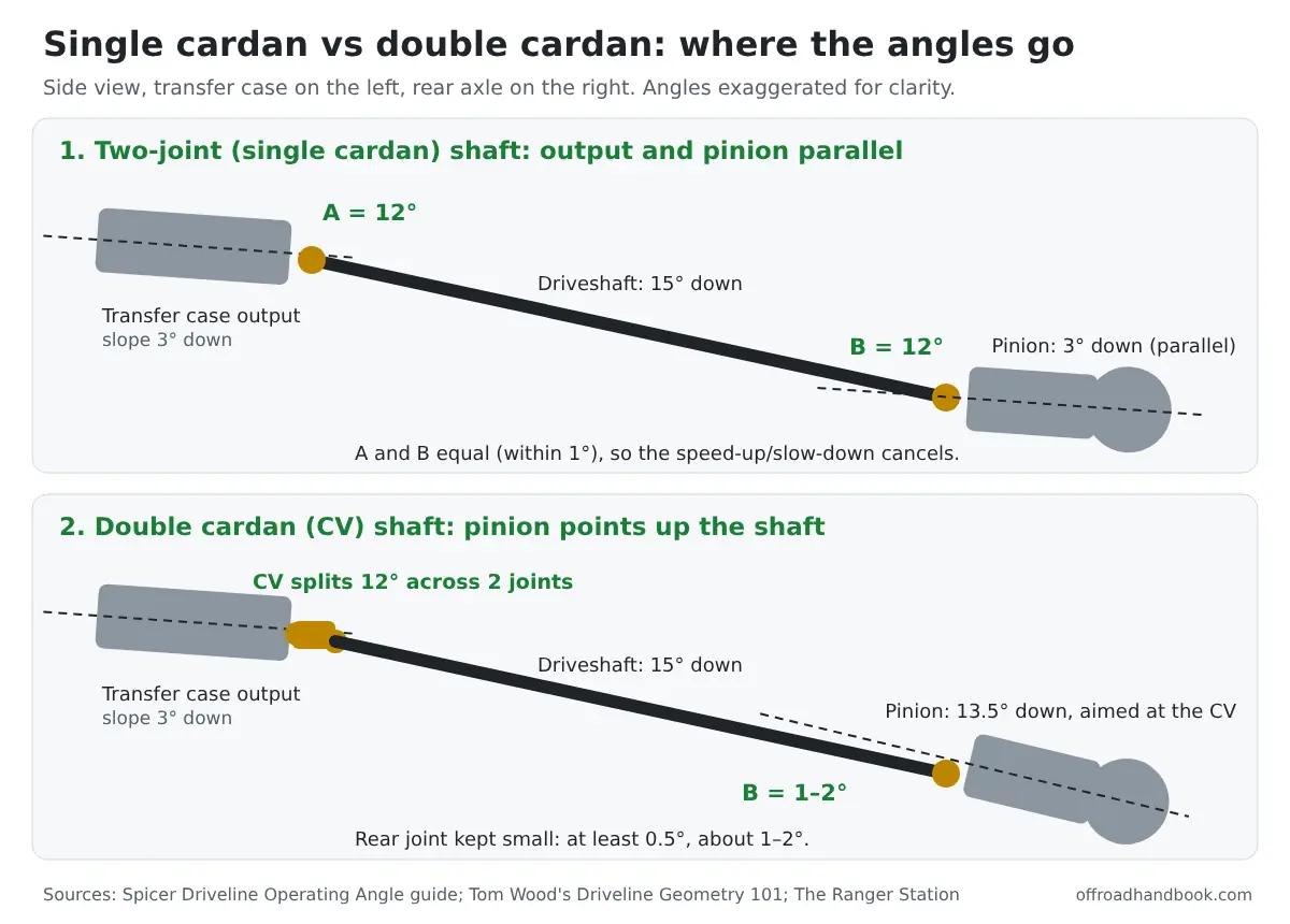
A single U-joint working at an angle makes the output shaft speed up and slow down twice per turn. On a two-joint shaft, the second joint undoes that wobble only when it works at the same angle as the first. Tom Wood's explains it in Driveline Geometry 101. That's why the transfer case output and pinion end up parallel.
A CV shaft does the cancelling inside its double joint at the transfer case. The single joint at the axle has no partner, so its angle has to stay small. That means rolling the pinion up until it points almost straight up the shaft.
| Rule | Two-joint (single cardan) | Double cardan (CV) |
|---|---|---|
| Pinion target | Parallel to transfer case output, so both joint angles are equal | Aimed up the driveshaft, 1–2° below the shaft line |
| Angle match | Front and rear joints within 1° of each other (0.5° for a shaft ahead of the transfer case) | Not required; the CV splits its angle across two joints |
| Minimum angle | 0.5° per joint | 0.5° at the rear joint, about 1–2° in practice |
| Vibration-free target | 3° or less per joint | Rear joint as small as practical |
| Absolute max | Spicer's speed chart (11.5° at 1,500 rpm down to 3.2° at 5,000 rpm) | Same chart applies to each joint |
| Mechanical binding | Most shafts bind around 25–30°; Tom Wood's warns never to run near that, and leave room for droop, axle wrap and frame flex | |
One myth worth dropping: a CV shaft doesn't let you run steeper. Tom Wood's points out that some CV joints actually bind at a smaller angle than a plain U-joint, and the longer CV assembly shortens the shaft's run, which makes the angle steeper still.
What a CV buys you is smoothness and joint life at angles that would shake a two-joint shaft.
For the CV pinion offset, The Ranger Station says to set the pinion 1–2° lower than the driveshaft so it has room to twist up under acceleration. Tom Wood's simply calls for minimal angle at the differential end. Both agree the pinion follows the shaft, not the transfer case.
How to Measure Driveshaft Angles at Home
All you need is an angle finder that reads to ¼°. A magnetic digital angle gauge sticks to yokes and the shaft tube, which makes this a one-person job (check the current price on Amazon). A cheap bubble-and-dial angle finder from a hardware store works too.
- Set tire pressures to normal and park on ground that's as level as possible, front to back and side to side (Spicer's measuring guide). Keep the truck on its wheels so the suspension sits at ride height.
- Transfer case output: read off the flat, machined face of the output yoke or flange. Any machined face there is either square or parallel to the shaft centerline.
- Driveshaft: put the gauge on the tube itself, on a straight section away from welds and balance weights.
- Pinion: read off the pinion yoke or flange, or bridge the gauge across two differential cover bolts stacked one above the other.
- Write down each number with its direction (down or up toward the axle) and enter them in the calculator.
- Repeat with the truck loaded the way you drive it. Spicer suggests checking both unloaded and loaded, since some vibrations show up only with weight in the bed.
Odd readings usually mean the gauge is turned sideways. Tom Wood's measuring guide says to subtract from 90 if you read something like 83° (call it 7°), or subtract 360 from a reading like 381° (call it 21°).
The same guide gives typical ranges: transfer cases 0–10°, driveshafts 10–40°, pinions 0–30°. A number outside those ranges is worth measuring again.
How Fast Does Your Driveshaft Spin at Highway Speed?
This is the part most angle guides skip, and it's why the same 7° angle feels fine on the trail and buzzes at 75 mph. Spicer's maximum angle depends on driveshaft rpm, and that comes straight from speed, tire size and axle ratio.
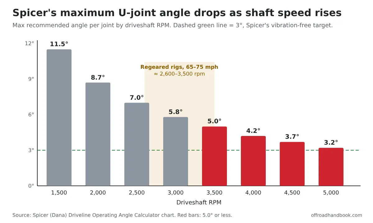
Bigger tires slow the shaft down, and the deeper gears you add to make up for them speed it right back up. A properly regeared rig ends up spinning its driveshafts about as fast as stock at the same road speed. That puts most of them in the 5.0° row of Spicer's chart at 75 mph.
| Tire / axle ratio | Driveshaft rpm at 65 mph | Driveshaft rpm at 75 mph | Spicer max at 75 mph | Spicer max at 80 mph |
|---|---|---|---|---|
| 31 in / 3.73 | 2,629 | 3,033 | 5.0° | 5.0° |
| 33 in / 4.10 | 2,715 | 3,132 | 5.0° | 5.0° |
| 35 in / 4.56 | 2,847 | 3,284 | 5.0° | 4.2° |
| 37 in / 4.88 | 2,882 | 3,325 | 5.0° | 4.2° |
| 37 in / 5.13 | 3,029 | 3,495 | 5.0° | 4.2° |
| 40 in / 5.38 | 2,939 | 3,391 | 5.0° | 4.2° |
I built this table by running each tire-and-gear pairing through that formula and matching the result to the next-higher rpm row in Spicer's chart instead of interpolating between rows, so the limits lean conservative. The pairings are common combinations, not specs for any one vehicle.
Here's the takeaway. A lifted two-joint shaft running 8–12° at each end is beyond Spicer's limit at highway speed, even if the angles match perfectly. That's the point where a CV shaft or less lift starts to make sense. If you still need to pick gears, the regear calculator shows which ratio brings your rpm back to stock.
How to Fix Bad Driveshaft Angles After a Lift
Match the fix to what you measured. Don't throw parts at a vibration before you have three numbers on paper; "tuning it out" without measuring is one of the common mistakes Tom Wood's lists in its pinion angle adjustment guide.
| What you measured | Likely fix | Notes |
|---|---|---|
| Two-joint shaft, angles differ by more than 1°, leaf springs | Tapered axle shims to rotate the pinion | Pick the shim angle from your measurement, install it the right way around and re-torque the U-bolts |
| Two-joint shaft, angles differ by more than 1°, link suspension | Adjustable control arms | Lets you rotate the axle without moving the wheelbase much |
| Angles match but each joint is over Spicer's max for your highway rpm | Double cardan (CV) shaft, then reset the pinion to point up the shaft | Expect to change pinion angle when you convert |
| CV shaft, pinion pointing at the transfer case or above the shaft line | Rotate the pinion up until it sits 1–2° below the shaft | Rotating the axle moves the fill plug; make sure the gear oil level is still right |
| Front shaft out of spec | Compromise between pinion angle and caster, or cut and turn the knuckles | Rotating a front axle changes caster and steering return |
The front shaft is where most builds settle for "good enough." Rotating a solid front axle to fix pinion angle also rolls the caster back, which hurts straight-line stability. Tom Wood's notes most builders do what the factories do: get the faster, busier rear shaft right and live with a less-than-perfect front shaft that turns less often.
On leaf-sprung trucks, plan for axle wrap too. Under hard throttle, the axle twists the pinion upward, which is exactly why the CV setting leaves the pinion 1–2° low. A vibration that comes in mainly under throttle on a leaf-sprung truck can point to wrap.
A driveline vibration isn't the only thing a lift can bring on. The Jeep lift kit problem guide covers wander, death wobble and rubbing, and the guide to shaking in 4-wheel drive covers vibration that only shows up with the front shaft turning.
Why Angles Matter for U-Joint Life
Spicer says any operating angle over 3° lowers U-joint life and may cause vibration. Tom Wood's puts numbers on it: a U-joint's rating assumes a 3° angle at 3,000 rpm, and doubling the angle roughly halves its life.
Too little angle isn't the goal either. Spicer sets a minimum of 0.5° at each joint, so a dead-straight two-joint shaft is not what you're after.
Check your angles again with the axles at full droop, too. Tom Wood's warns that a shaft running near its binding angle can fail suddenly when droop, frame flex or axle roll adds a few more degrees on the trail. Make sure the shaft turns freely at full droop before you call the job done.
Driveshaft Angle FAQ
Should the pinion angle match the driveshaft angle?
Only with a double cardan (CV) shaft, and even then it sits 1–2° below the shaft line. With a two-joint shaft, the pinion should be parallel to the transfer case or transmission output so both joint angles are equal.
What is the maximum U-joint angle?
Spicer's chart allows 11.5° at 1,500 driveshaft rpm, 5.8° at 3,000 rpm, 5.0° at 3,500 rpm and 3.2° at 5,000 rpm. For vibration-free running and long joint life, Spicer's target is 3° or less.
How many degrees of lift before I need a CV driveshaft?
There's no fixed lift height, because wheelbase and shaft length change the angle. Measure, then compare each joint angle with Spicer's maximum for your highway driveshaft rpm. If the angles are over that limit even when they match, a CV shaft is the usual answer.
Do I measure driveshaft angles with the vehicle on a lift?
Measure with the weight on the tires, on level ground, at normal tire pressure, so the suspension sits at ride height. A frame-contact lift lets the axles hang and changes the angles you're trying to read.

I'm Suryashankar Dasgupta, the founder of Off-Road Handbook. I've been off-roading for years in the USA, including California and Texas, and have ridden mountain and desert terrain abroad. I've also driven a Jeep Compass for more than seven years, so I know the day-to-day side of Jeep ownership first-hand, from the Uconnect screen to the warning lights. Every guide here is researched from manufacturer owner's manuals, NHTSA recall and service-bulletin records and other trusted sources, checked against them before it is published, and corrected when we find a mistake. You can read how we work in our editorial policy: https://offroadhandbook.com/editorial-policy/
Like our off-road guides? Add Off-Road Handbook as a Google Preferred Source so our latest Jeep, ATV, UTV, trail, recovery, and off-road troubleshooting articles can appear more often in your Google Search experience.
Add us as a Preferred Source